I have had a set of Intex Wireless Roaming Headphones lying around the house for a couple of years. They consist of a receiver (headphones) and a separate transmitter. The headphones include an FM receiver powered by two AAA batteries with reset and scan buttons for normal FM operation, and of course volume control. The separate transmitter comes with audio and microphone jack ports and is also powered by two AAA batteries. It also has a DC port as an alternative power source option. Here’s how it looks:
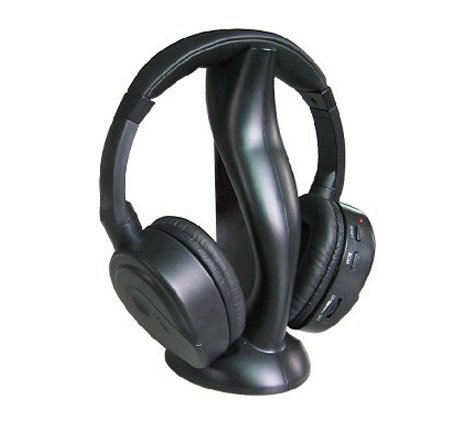
How it works is that you connect your audio source to either the transmitter or the headphones with an aux cable. If you go the transmitter way, to listen to the audio, you press the reset button then the scan button on the headphones. The headphones then receive the audio wireless from the transmitter. That’s how I had been using the headphones until I got the HackRF One. What was taking place behind the scenes had to be investigated…naturally :).
The wireless operation of the headsets provided the first clue. The pressing of the reset button followed by the scan button to get the audio from the transmitter meant that the communication was FM. It also followed that the frequency in use was lower than the normal FM frequency band as the audio was heard immediately after the first scan button press.
It was then time to fire up the HackRF One and confirm this. I therefore opened gqrx and tuned to around 87.5MHz. The normal FM band is from 87.5 to 108MHz so I wanted to observe the frequencies just before 87.5MHz. What remained was to connect an audio source to the transmitter and observe what happened on the gqrx display. What was observed is a strong signal peaking at 86.5MHz as shown below:
![]()
Tuning to that frequency and listening to the audio output confirmed that it was the audio from the transmitter being received. Further investigation revealed that the receiver had a frequency range from 84Mhz to 108MHz. The makers of the headsets used the fact that most recievers are tuned to only receive 87.5MHz as the lower end frequency. The 86.5MHz the headsets use is therefore not received on normal FM receivers otherwise anyone listening to FM radio could listen in.
This is where the fun begins
It was now time to open up the headphones and transmitter to see what the actual circuit boards looked like. The headphones’ circuit board as expected is just a simple FM receiver that can be tuned to lower frequencies than normal FM receivers. The interesting circuit board is the one from the transmitter. Its input audio source is one of three options: an audio jack, a microphone jack, or an inbuilt microphone. The option to use is selected using a slide switch. The frequency it transmits on is controlled by a trimmer capacitor set in place using epoxy.
The circuit board was relatively small in size so I separated it from its casing. I then fashioned a micro-usb power port by patching together the two power cables meant for the triple AAA batteries with the end of a female micro-usb cable. Finally I cleared away the epoxy on the trimmer capacitor to enable tuning of the transmit frequency :). This is how the end product looks like:
![]()
I had an old powerbank that had some issues so I decided to re-purpose it. I took out the rechargeable batteries patched them up to the end of a USB cable to fashion a portable battery pack. The charging circuit board would come in handy for recharging the batteries :).
Here’s the charging circuit board:
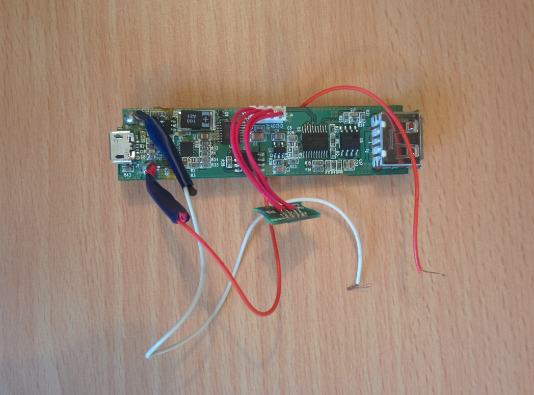
Here’s the transmitter hooked up to the rechargeable batteries:
![]()
Testing it out
With the transmitter hooked up to the batteries and gqrx running, it was time to test out tuning to different frequencies. Adjusting the transmit frequency by turning the trimmer capacitor with a small screw driver works as expected. Here’s the frequency adjusted to 88.5MHz, which can be listened to on normal FM receivers.
![]()
If we set the slide switch on the transmitter to microphone, the transmitter listens to sounds around it and transmits on the frequency we set. Its frequency response range is 20 - 20000Hz which is the human hearing range, making it optimized to capture human voice :).
You can either use the internal mic on the circuit board or connect an external one to the mic jack to meet your specific needs.
With the micro-usb power cable I added, you can power it using the rechargeable batteries, computer/phone USB ports or the normal USB chargers. The frequency can be tuned using the trimmer capacitor and listened to on a normal FM receiver, or tuned to frequencies below the FM band to prevent eavesdropping by everyone else. The range of the transmitter is about 30m, but this could easily be increased by having a retransmitter within range. The transmitter circuit board is small enough to be easily concealed. Creative ways can also be employed like placing it in a hard disk case as I’ve done below :)
![]()
![]()
Can it DOS?
Set the slide switch to audio and you can play audio from your preferred audio source (say your phone) using an aux cable to the frequency you tune the transmitter to. If that frequency is allocated to a radio station, then anyone tuned to that station within 30m listens to what you play (legal issues ensue). With its portable nature, you become a mobile radio station DOSer.
The cost of the headsets is about 10 dollars and for that you can come up with some creative ways of making use of the transmitter. You can continue using the headphones independently with an aux cable or listening to FM radio.
For now I plan on replacing the trimmer capacitor with a more flexible one, and hopefully interface it with a smartphone to provide an interface to control the frequency :).
Till next time, happy hacking!